
Spray ball SK
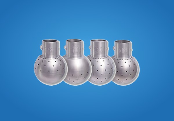
With push-in connection, thread or weld-on end
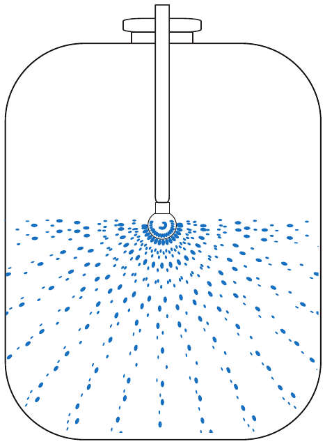
- Standard spray ball for CIP cleaning of vessels and tanks
- Sizes DN8 to DN50, four spray patterns (360°, 270° top, 180° top, 180° bottom)
- Connection: push-in connection, thread G 1/4″ to G 2″ or weld-on end
- Material 1.4404 (316L), working pressure 1 – 2.5 bar
| Property | Value |
|---|---|
| Application: | Standard spray ball for CIP cleaning of vessels and tanks |
| Sizes: | Push-in connection DN8 to DN50; thread G 1/4" to G 2" or weld-on end DN8 to DN50 |
| Spray patterns: | 360°, 270° top, 180° top, 180° bottom (with drain hole) |
| Working pressure: | 1 – 2.5 bar |
| Material: | 1.4404 (316L) |
Material: standard 1.4404 (316L), optionally 1.4571, 1.4435, 1.4539, 2.4602 etc. Surface: ground, outside Ra ≤ 0.2 – 0.3 µm, optionally electropolished. Inspection certificate 3.1 available. The spray balls comply with Regulation (EC) No 1935/2004. Manufactured according to DIN EN ISO 9001:2015.
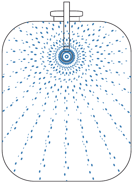
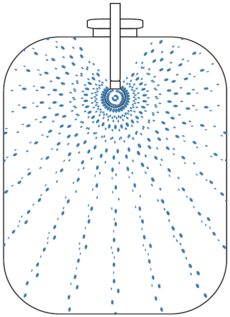
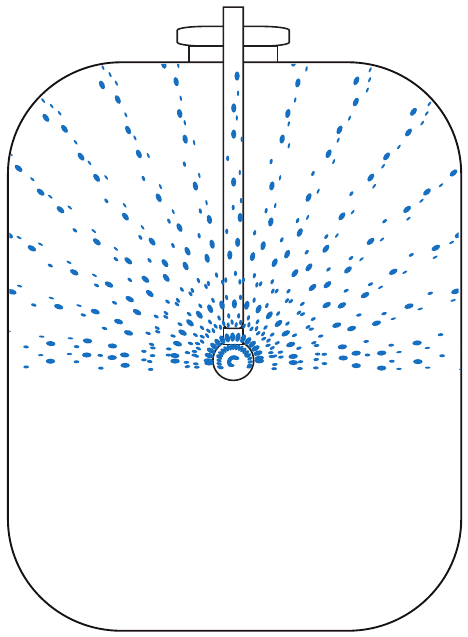
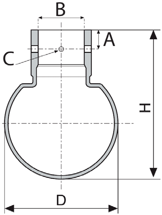
Connection: push-in connection, secured with split pin or retaining clamp. Pipe: DIN 11850 Series 1 / Series 2.
| Size | Hole ØE (mm) | Spray circle Ø (m) | Flow rate m³/h | A (mm) | ØB (mm) | ØC (mm) | ØD (mm) | H (mm) | Pin (mm) | Clamp (mm) | |||||||
|---|---|---|---|---|---|---|---|---|---|---|---|---|---|---|---|---|---|
| 360° | 270° top | 180° top | 180° bottom | ||||||||||||||
| 1 bar | 2.5 bar | 1 bar | 2.5 bar | 1 bar | 2.5 bar | 1 bar | 2.5 bar | ||||||||||
| DN8 | 0.8 | 0.4 | 0.7 | n. s. | – | – | – | – | – | – | 7.5 | 8.2 | 2.5 | 20 | 32.8 | 0.8 | – |
| DN10 | 1.2 | 0.8 | 2.4 | n. s. | – | – | – | – | – | – | 8.5 | 12.3 | 2.5 | 24 | 37 | 1.8 | – |
| DN15 | 1.3 | 1.5 | 4 | n. s. | 3 | n. s. | 2 | n. s. | 2 | n. s. | 9 | 18.3 | 2.5 | 30 | 38.5 | 2.2 | 2.0 |
| DN20 | 2.0 | 2.5 | 8 | 13 | 8 | 12 | 5 | 9 | 6 | 9 | 11 | 22.3 | 2.5 / 3.5 | 39 | 53 | 2.8 | 2.0 |
| DN25 | 2.0 | 3 | 11 | 17 | 11 | 17 | 9 | 14 | 7 | 11 | 16 | 28.3 | 3 | 64 | 84.5 | 2.2 | 2.0 |
| DN25/1 | 3.0 | 4 | 18 | 28 | 16 | 26 | 14 | 23 | 12 | 19 | 16 | 28.3 | 3 | 64 | 84.5 | 2.2 | 2.0 |
| DN32 | 2.0 | 3.5 | 13 | 20 | 11 | 18 | 10 | 16 | 8 | 13 | 16 | 34.3 | 2.5 / 3.5 | 64 | 80.5 | 2.8 | 2.0 |
| DN32/1 | 3.0 | 4 | 21 | 34 | 21 | 33 | 17 | 26 | 14 | 23 | 16 | 34.3 | 2.5 / 3.5 | 64 | 80.5 | 2.8 | 2.0 |
| DN40 | 2.0 | 3.5 | 11 | 19 | 11 | 16 | 10 | 15 | 11 | 16 | 18 | 40.3 | 2.5 / 3.5 | 64 | 79.5 | 2.8 | 2.0 |
| DN40/1 | 3.0 | 4 | 22 | 36 | 20 | 33 | 15 | 24 | 14 | 23 | 18 | 40.3 | 2.5 / 3.5 | 64 | 79.5 | 2.8 | 2.0 |
| DN50 | 2.2 | 5 | 28 | 42 | 27 | 42 | 20 | 30 | 17 | 27 | 25 | 52.3 | 3.5 / 3.5 | 90 | 118 | 2.8 | 2.5 |
| DN50/1 | 3.0 | 6 | 49 | 69 | 45 | 67 | 31 | 51 | 30 | 49 | 25 | 52.3 | 3.5 / 3.5 | 90 | 118 | 2.8 | 2.5 |
| DN50/2 | – | 10 | – | – | – | – | 35 | 58 | – | – | 25 | 52.3 | 3.5 / 3.5 | 90 | 118 | 2.8 | 2.5 |
Flow rates and spray circles are approximate values. Recommended working pressure 1 – 2.5 bar. Other spray angles and special designs on request.
n. s. = not suitable at 2.5 bar · on req. = on request · – = spray pattern not available for this size
Securing the push-in connection
The spray ball is pushed onto the connecting pipe and secured with a retaining clamp or a split pin. The wire thickness of the securing element for each size is given in the table (columns Pin / Clamp). The annular gap between socket and connecting pipe serves to clean the connecting pipe.
The data, technical data and information presented do not release the user from the obligation to check the suitability of the products supplied for the intended application. All information is without guarantee. (Status: 03.10.2026)
Connection: thread G 1/4" to G 2" or weld-on end DN8 to DN50. Surface: ground.
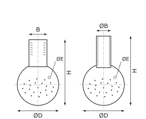
Threaded connection – G 3/8" with male thread, other sizes with female thread
| Size | Hole ØE (mm) | Spray circle Ø (m) | Flow rate m³/h | B (thread) | ØD (mm) | H (mm) | |||||||
|---|---|---|---|---|---|---|---|---|---|---|---|---|---|
| 360° | 270° top | 180° top | 180° bottom | ||||||||||
| 1 bar | 2.5 bar | 1 bar | 2.5 bar | 1 bar | 2.5 bar | 1 bar | 2.5 bar | ||||||
| G 1/4" | 1.3 | 1.5 | 3.2 | n. s. | 2.6 | n. s. | 2.3 | n. s. | 2.1 | n. s. | G 1/4" | 30 | 39.2 |
| G 3/8" | 1.3 | 1.5 | 3.4 | n. s. | 2.8 | n. s. | 2.3 | n. s. | 2.2 | n. s. | G 3/8" | 30 | 39.5 |
| G 1/2" | 2.0 | 2.5 | 7.7 | 11.6 | 7.1 | 10.4 | 5.2 | 7.7 | 5.1 | 7.7 | G 1/2" | 40 | 49.5 |
| G 3/4" | 2.0 | 3 | 8.5 | 12.9 | 6.8 | 10.4 | 5.2 | 7.9 | 4.7 | 7.1 | G 3/4" | 64 | 81 |
| G 1" | 2.0 | 4 | 8.1 | 12.2 | 7.2 | 10.9 | 5 | 7.4 | 4.7 | 7.2 | G 1" | 64 | 80.5 |
| G 1 1/2" | 2.2 | 3.5 | 23.6 | on req. | 22 | on req. | 12.5 | on req. | 17.9 | on req. | G 1 1/2" | 90 | 104 |
| G 2" | 2.2 | 4 | 22.4 | on req. | 21.7 | on req. | 12.8 | on req. | 17.9 | on req. | G 2" | 90 | 116 |
Weld-on end – B = connection diameter in mm
| Size | Hole ØE (mm) | Spray circle Ø (m) | Flow rate m³/h | B (mm) | ØD (mm) | H (mm) | |||||||
|---|---|---|---|---|---|---|---|---|---|---|---|---|---|
| 360° | 270° top | 180° top | 180° bottom | ||||||||||
| 1 bar | 2.5 bar | 1 bar | 2.5 bar | 1 bar | 2.5 bar | 1 bar | 2.5 bar | ||||||
| DN8 | 0.8 | 0.4 | 0.7 | n. s. | – | – | – | – | – | – | 8.2 | 20 | 32.8 |
| DN10 | 1.2 | 0.8 | 2.4 | n. s. | – | – | – | – | – | – | 12.3 | 24 | 37 |
| DN15 | 1.3 | 1.5 | 4 | n. s. | 3 | n. s. | 2 | n. s. | 2 | n. s. | 18.3 | 30 | 38.5 |
| DN20 | 2.0 | 2.5 | 8 | 13 | 8 | 12 | 5 | 9 | 6 | 9 | 22.3 | 39 | 53 |
| DN25 | 2.0 | 3 | 11 | 17 | 11 | 17 | 9 | 14 | 7 | 11 | 28.3 | 64 | 84.5 |
| DN25/1 | 3.0 | 4 | 18 | 28 | 16 | 26 | 14 | 23 | 12 | 19 | 28.3 | 64 | 84.5 |
| DN32 | 2.0 | 3.5 | 13 | 20 | 11 | 18 | 10 | 16 | 8 | 13 | 34.3 | 64 | 80.5 |
| DN32/1 | 3.0 | 4 | 21 | 34 | 21 | 33 | 17 | 26 | 14 | 23 | 34.3 | 64 | 80.5 |
| DN40 | 2.0 | 3.5 | 11 | 19 | 11 | 16 | 10 | 15 | 11 | 16 | 40.3 | 64 | 79.5 |
| DN40/1 | 3.0 | 4 | 22 | 36 | 20 | 33 | 15 | 24 | 14 | 23 | 40.3 | 64 | 79.5 |
| DN50 | 2.2 | 5 | 28 | 42 | 27 | 42 | 20 | 30 | 17 | 27 | 52.3 | 90 | 118 |
| DN50/1 | 3.0 | 6 | 49 | 69 | 45 | 67 | 31 | 51 | 30 | 49 | 52.3 | 90 | 118 |
Flow rates and spray circles are approximate values. Recommended working pressure 1 – 2.5 bar. Other spray angles and special designs on request.
n. s. = not suitable at 2.5 bar · on req. = on request · – = spray pattern not available for this size
Special spray balls to your specifications in shape, material and hole pattern
In addition to the standard sizes, spray balls for special requirements are available:
- Design to your specifications
- Manufacture to your drawing
- Replica of an existing spray head by 3D scan
- Individual spray angles and special materials
The data, technical data and information presented do not release the user from the obligation to check the suitability of the products supplied for the intended application. All information is without guarantee. (Status: 03.10.2026)
Newsletter
New products, application examples and offers in industrial cleaning technology – a few times a year, straight to your inbox.