
Static spray balls with pin connection (R-clip)
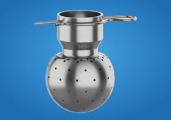
3A · inch connection (R-clip)
- Ball 1.4404 (316L), R-clip 1.4401, ground, outside Ra ≤ 0.8 µm
- Inch OD connection 1″, 1½” and 2″ with R-clip
- Types A/LA 360°, B 192° – 194°, G 206° – 246°, L 188°
- Recommended operating pressure 1.0 to 2.5 bar g
3A · inch connection (R-clip) – DIN 10357 Series C / DIN 11866 Series C / ASME-BPE 2022
| Property | Value |
|---|---|
| Connection: | inch OD / R-clip |
| Ball material: | 1.4404 (316L) |
| R-clip material: | 1.4401 |
| Surface: | ground, outside Ra ≤ 0.8 µm |
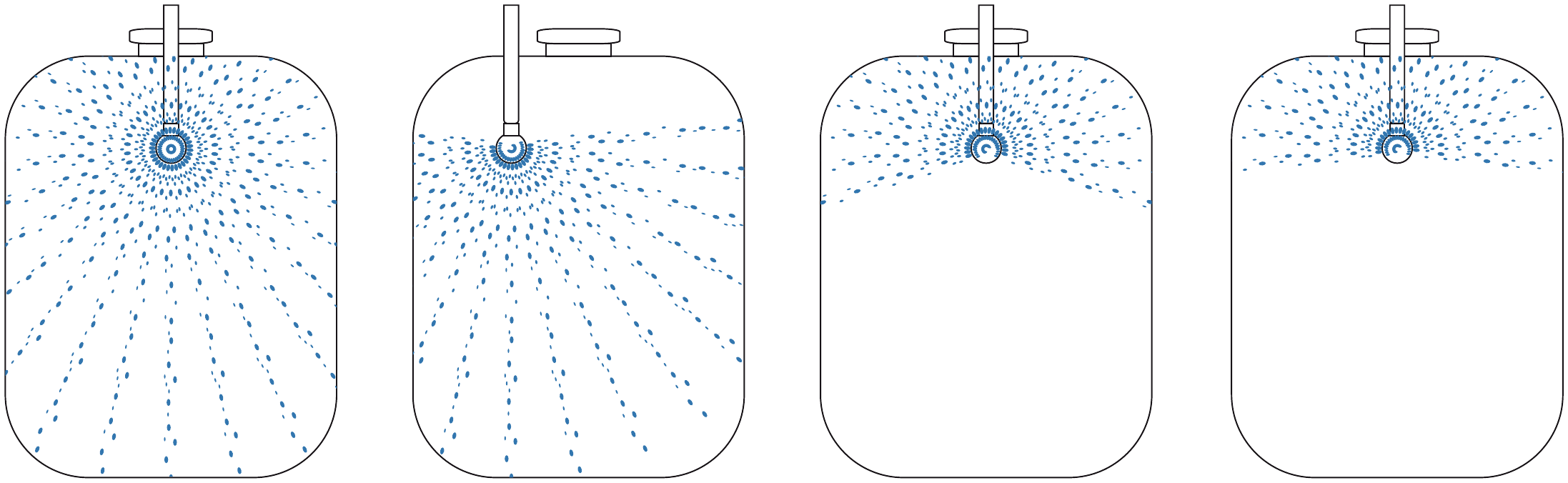
Spray patterns and application
| Type | Spray angle | Application |
|---|---|---|
| Type A/LA | 360° | vertical and horizontal tanks |
| Type B | 192° – 194° | directed downwards |
| Type G | 206° – 246° | directed upwards |
| Type L | 188° | directed upwards, horizontal tanks |
| Type | Spray angle | Cleaning Ø (m) | Flow rate m³/h at pressure (bar) | DA (mm) | LA (mm) | PL (mm) | Connection | Order code | |||||
|---|---|---|---|---|---|---|---|---|---|---|---|---|---|
| 1.0 | 1.5 | 1.8 | 2.0 | 2.2 | 2.5 | ||||||||
| A 1-1,0 | 360° | 1.5 – 2.0 | 3.0 | 3.7 | 4.0 | 4.2 | 4.4 | 4.7 | 68 | 84 | 78 | 1" (25.4) | PF-253-112.21 |
| A 1-1,0 | 360° | 1.5 – 2.0 | 3.0 | 3.7 | 4.0 | 4.2 | 4.4 | 4.7 | 68 | 92 | 101 | 1½" (38.1) | PF-253-112.23 |
| A 1-1,5 | 360° | 1.8 – 3.0 | 7.0 | 8.6 | 9.4 | 9.9 | 10.4 | 11.1 | 68 | 84 | 78 | 1" (25.4) | PF-253-112.22 |
| A 1-1,5 | 360° | 1.8 – 3.0 | 7.0 | 8.6 | 9.4 | 9.9 | 10.4 | 11.1 | 68 | 92 | 101 | 1½" (38.1) | PF-253-112.24 |
| A1 | 360° | 2.0 – 3.0 | 9.8 | 12.0 | 13.1 | 13.9 | 14.5 | 15.5 | 68 | 84 | 78 | 1" (25.4) | PF-253-112.06 |
| A1 | 360° | 2.0 – 3.0 | 9.8 | 12.0 | 13.1 | 13.9 | 14.5 | 15.5 | 68 | 92 | 101 | 1½" (38.1) | PF-253-112.25 |
| A 1-1 | 360° | 2.5 – 3.5 | 12.8 | 15.7 | 17.2 | 18.1 | 19.0 | 20.2 | 68 | 84 | 78 | 1" (25.4) | PF-253-112.07 |
| A 1-1 | 360° | 2.5 – 3.5 | 12.8 | 15.7 | 17.2 | 18.1 | 19.0 | 20.2 | 68 | 92 | 101 | 1½" (38.1) | PF-253-112.26 |
| A 1-2 | 360° | 3.0 – 4.0 | 15.3 | 18.7 | 20.5 | 21.6 | 22.6 | 24.1 | 68 | 84 | 78 | 1" (25.4) | PF-253-112.08 |
| A 1-2 | 360° | 3.0 – 4.0 | 15.3 | 18.7 | 20.5 | 21.6 | 22.6 | 24.1 | 68 | 92 | 101 | 1½" (38.1) | PF-253-112.27 |
| A2 | 360° | 3.5 – 5.0 | 21.9 | 26.8 | 29.4 | 31.0 | 32.5 | 34.6 | 93 | 113.5 | 117 | 2" (50.8) | PF-253-112.09 |
| A 2-1 | 360° | 4.0 – 6.0 | 28.4 | 34.8 | 38.2 | 40.2 | 42.2 | 45.0 | 93 | 113.5 | 117 | 2" (50.8) | PF-253-112.10 |
| A 2-2 | 360° | 5.0 – 7.0 | 35.6 | 43.6 | 47.8 | 50.3 | 52.8 | 56.3 | 93 | 113.5 | 117 | 2" (50.8) | PF-253-112.11 |
| A 2-3 | 360° | 6.0 – 8.0 | 40.9 | 50.1 | 54.9 | 57.8 | 60.7 | 64.7 | 93 | 113.5 | 117 | 2" (50.8) | PF-253-112.12 |
| B1 | 192° | 2.0 – 3.0 | 9.5 | 11.6 | 12.7 | 13.4 | 14.1 | 15.0 | 68 | 84 | 78 | 1" (25.4) | PF-253-112.28 |
| B1 | 192° | 2.0 – 3.0 | 9.5 | 11.6 | 12.7 | 13.4 | 14.1 | 15.0 | 68 | 92 | 101 | 1½" (38.1) | PF-253-112.29 |
| B2 | 194° | 3.5 – 5.0 | 22.4 | 27.4 | 30.1 | 31.7 | 33.2 | 35.4 | 93 | 113.5 | 117 | 2" (50.8) | PF-253-112.30 |
| B 2-3 | 194° | 6.0 – 8.0 | 42.2 | 51.7 | 56.6 | 59.7 | 62.6 | 66.7 | 93 | 113.5 | 117 | 2" (50.8) | PF-253-112.31 |
| G1 | 206° | 2.0 – 3.0 | 9.2 | 11.3 | 12.3 | 13.0 | 13.6 | 14.5 | 68 | 84 | 78 | 1" (25.4) | PF-253-112.13 |
| G1 | 206° | 2.0 – 3.0 | 9.2 | 11.3 | 12.3 | 13.0 | 13.6 | 14.5 | 68 | 92 | 101 | 1½" (38.1) | PF-253-112.32 |
| G 1-1 | 206° | 2.5 – 3.5 | 11.2 | 13.7 | 15.0 | 15.8 | 16.6 | 17.7 | 68 | 84 | 78 | 1" (25.4) | PF-253-112.14 |
| G 1-1 | 206° | 2.5 – 3.5 | 11.2 | 13.7 | 15.0 | 15.8 | 16.6 | 17.7 | 68 | 92 | 101 | 1½" (38.1) | PF-253-112.33 |
| G 1-2 | 206° | 3.0 – 4.0 | 14.5 | 17.8 | 19.5 | 20.5 | 21.5 | 22.9 | 68 | 84 | 78 | 1" (25.4) | PF-253-112.15 |
| G 1-2 | 206° | 3.0 – 4.0 | 14.5 | 17.8 | 19.5 | 20.5 | 21.5 | 22.9 | 68 | 92 | 101 | 1½" (38.1) | PF-253-112.34 |
| G2 | 246° | 3.5 – 5.0 | 20.1 | 24.6 | 27.0 | 28.4 | 29.8 | 31.8 | 93 | 113.5 | 117 | 2" (50.8) | PF-253-112.16 |
| G 2-1 | 246° | 4.0 – 6.0 | 26.8 | 32.8 | 36.0 | 37.9 | 39.8 | 42.4 | 93 | 113.5 | 117 | 2" (50.8) | PF-253-112.17 |
| G 2-2 | 246° | 5.0 – 7.0 | 34.7 | 42.5 | 46.6 | 49.1 | 51.5 | 54.9 | 93 | 113.5 | 117 | 2" (50.8) | PF-253-112.18 |
| G 2-3 | 246° | 6.0 – 8.0 | 41.0 | 50.2 | 55.0 | 58.0 | 60.8 | 64.8 | 93 | 113.5 | 117 | 2" (50.8) | PF-253-112.19 |
| L1 | 188° | 2.5 – 3.0 | 8.6 | 10.5 | 11.5 | 12.2 | 12.8 | 13.6 | 68 | 84 | 78 | 1" (25.4) | PF-253-112.35 |
| L1 | 188° | 2.5 – 3.0 | 8.6 | 10.5 | 11.5 | 12.2 | 12.8 | 13.6 | 68 | 92 | 101 | 1½" (38.1) | PF-253-112.38 |
| LA 1-1,0 | 360° | 1.5 – 2.5 | 5.5 | 6.7 | 7.4 | 7.8 | 8.2 | 8.7 | 68 | 84 | 78 | 1" (25.4) | PF-253-112.36 |
| LA 1-1,0 | 360° | 1.5 – 2.5 | 5.5 | 6.7 | 7.4 | 7.8 | 8.2 | 8.7 | 68 | 92 | 101 | 1½" (38.1) | PF-253-112.39 |
| LA 1-1,5 | 360° | 2.5 – 3.0 | 11.0 | 13.5 | 14.8 | 15.6 | 16.3 | 17.4 | 68 | 84 | 78 | 1" (25.4) | PF-253-112.37 |
| LA 1-1,5 | 360° | 2.5 – 3.0 | 11.0 | 13.5 | 14.8 | 15.6 | 16.3 | 17.4 | 68 | 92 | 101 | 1½" (38.1) | PF-253-112.40 |
- For electropolished spray balls, the flow rate is approx. 15 – 20 % higher than stated in the table.
- Recommended operating pressure 1.0 to 2.5 bar g at the spray ball inlet. Guide value for cleaning liquid: 30 to 50 l/min per metre of tank circumference.
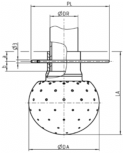
- PL = insertion depth. Installation dimensions a / b: 1" = 10 / 8 mm; 1½" = 5.5 / 10 mm; 2" = 10 / 20 mm.
- The annular gap between sleeve and outside diameter of the pipe serves to clean the insertion pipe. Spare R-clips: see special designs, spare parts and accessories.
The data, technical data and information presented do not release the user from the obligation to check the suitability of the products supplied for the intended application. All information is without guarantee. (Status: 03.10.2026)
R-clips for pin connection (with inspection certificate 3.1)
| Order code | R-clip for pin connection |
|---|---|
| 253-107.09 | R-clip 1" OD 3A · 1.4401 |
| 253-107.11 | R-clip 1½" OD 3A · 1.4401 |
| 253-107.10 | R-clip 2" OD 3A · 1.4401 |
Newsletter
New products, application examples and offers in industrial cleaning technology – a few times a year, straight to your inbox.