
High-pressure retractable unit
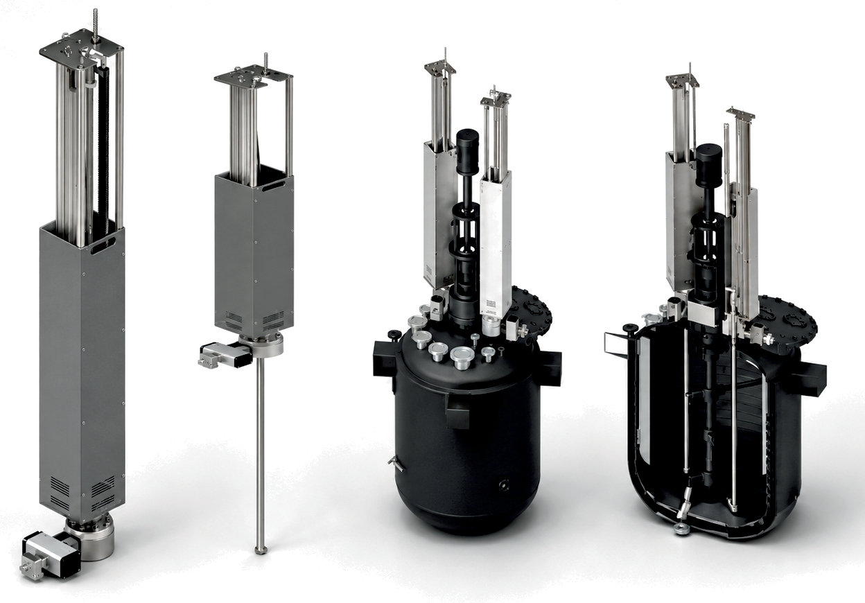
Automated CIP cleaning of tanks and reactors
- Stroke up to 3000 mm
- Pneumatic or electric cylinder
- RH cleaning head, 360°
- Up to 200 bar and 50 LPM
- Moves the cleaner into the tank and out again automatically
- Cleaning head driven by a compact water turbine
- Speed 10–30 rpm, adjustable
- Continuous or step-by-step travel with high positioning accuracy
- End positions detected by magnetic sensors
- Insertion opening from Ø 77 mm, flange mounting
- Control via the plant PLC or a separate module
- CE, ATEX (pneumatic version: zone 1)
| Technical data | Value |
|---|---|
| Linear drive: | pneumatic or electric cylinder |
| Stroke length: | up to 3000 mm (118 inch), longer on request |
| Rotary drive: | water-hydraulic (water turbine) |
| Cleaning head: | RH55 (spray head combination S-RH-55) |
| Speed: | 10 – 30 rpm, adjustable |
| Cleaning cycle: | 1.9 – 5.5 min (55 revolutions) |
| Working pressure: | 100 – 200 bar (1450 – 2900 psi) |
| Flow rate: | 14 – 50 LPM (3.7 – 13.2 US gpm) |
| Temperature: | −30 to +90 °C (−22 to +194 °F) |
| Jet coverage: | 360° |
| Nozzles: | 2 pcs., 0° / 5° / 15°, 1/8" |
| HP water connection: | 3/8" |
| Insertion opening: | min. Ø 77 mm (3.03 inch) |
| Mounting flange: | DN 100 / Ø 220 mm or adapted to the tank |
| Material: | stainless steel AISI 316 (cleaning head, connecting pipe) |
| Seals: | FPM (Viton®) / EPDM / FDA |
| Dimensions: | 300 × 294 mm (pneumatic version without ball valve), height depending on the tank |
| Weight: | approx. 113 kg (249 lbs) with 3000 mm stroke |
| Approvals: | CE, ATEX (pneumatic version: zone 1) |
| Item no.: | PR.000.074 / PR.000.075 |
| Variant linear drive: | pneumatic cylinder (compressed air 6 bar) or electric cylinder |
| Variant stroke length: | adapted to the tank, up to 3000 mm; longer on request |
| Variant cleaning positions: | number and position as required by the customer |
| Variant speed: | factory-set to the high-pressure supply, adjustable via three flow control nozzles |
| Variant seals: | FPM (Viton®), EPDM or FDA-compliant |
The specifications, technical data and information provided do not release the user from their own responsibility to check the supplied products for suitability for the intended application. All information is provided without guarantee. (Status: 02.10.2026)
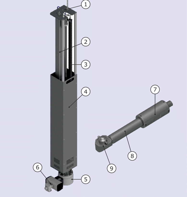
1 Top plate · 2 Linear cylinder (pneumatic or electric) · 3 Cable chain with high-pressure hose · 4 Housing · 5 Flange · 6 Ball valve with rotary actuator · 7 Water drive · 8 Connecting pipe · 9 RH cleaning head with 2 nozzles
Left: the retractable unit with the cleaner retracted; right: the cleaner.
- The linear cylinder moves the cleaner on a carriage into the tank and, after cleaning, out again – continuously or step by step and with high positioning accuracy.
- The cleaner is guided at the bottom by a bushing and fastened at the top to the carriage with a clamping ring. The cable chain carries the high-pressure water hose along.
- Only the cleaning head and the connecting pipe enter the tank; the retractable unit itself is mounted above the tank.
- A compact water turbine converts the flow of the cleaning water into a rotary motion. The connecting pipe transmits the motion and carries the high-pressure water to the cleaning head.
- A toothing on the cleaning head engages with a fixed toothing on the connecting pipe, so the head also rotates about a second axis offset by 90°. The nozzles thus move in a spherical pattern and, after one complete spray pattern, have reached every area of the tank (360°).
- Magnetic sensors (limit switches) report the end positions of the cylinder to the control system.
Control and installation
- Direct integration into the higher-level plant control system or separate module control of the cleaning system
- PLC-controlled, fully automatic sequence: time, temperature and flow rate are controlled; the cleaning process is reproducible and fully documented
- Mounted above the tank via a special flange; the position depends on tank size and internals
- Adaptable to the available space and the tank design; cleaning positions as required by the customer
- Fast installation and commissioning; expandable and connectable to existing automation systems
Automatic retractable units clean mixing plants, reactors and production and storage tanks reliably and without manual intervention – even with highly viscous products. They have proven themselves in this role for many years. Automation saves time and costs, and the cleaning result, safety and precision are the same in every cycle.
The retractable unit consists of a metal housing, a flange, a pneumatic or electric linear cylinder and the cleaner – a tank cleaner with water drive and RH cleaning head. The cleaner is guided at the bottom by a bushing and fastened at the top to the cylinder carriage with a clamping ring. A cable chain carries the high-pressure water hose. The cylinder moves the cleaner into the tank and out again; only the cleaning head and the connecting pipe enter the tank.
A compact water turbine uses the energy of the cleaning water not only for cleaning but also as the drive: the cleaning head rotates about two axes, and the nozzles cover the tank with 360° jet coverage. The speed is factory-set to the high-pressure supply and can be changed via flow control nozzles. The length and the number of cleaning positions are adapted to the tank. Thanks to the modular design, individual elements can be exchanged during servicing, so the unit is quickly back in operation. Contact us – we will design the retractable unit for your tank.
Your advantages
- Fully automatic, PLC-controlled cleaning without manual intervention – short downtimes
- Consistent results, independent of the operator
- Optimised water and energy consumption
- Meets the hygiene requirements of the food industry
- Reliable components, designed for a long service life; very quiet water drive
- Modular design: elements can be exchanged quickly during servicing
- Easy-to-maintain, safety-oriented design
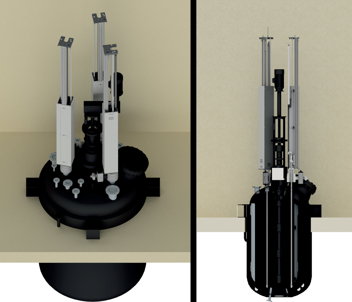
Reactor with three retractable units (left) and in section with the cleaners extended (right).
Design examples
Operating data of installed units with stroke lengths of 1000, 1650 and 1800 mm:
| Operating data | Value |
|---|---|
| Cleaning head: | 200 bar (2900 psi), 21 LPM (5.5 US gpm) |
| HP pump unit: | 400 V, 3-phase |
| Compressed air: | 6 bar (87 psi), pneumatic version |
| Supply voltage: | 24 V DC (pneumatic version), 325 V DC (electric version) |
RH cleaning head
- Hygienic head developed in accordance with the EHEDG design guidelines for hygiene in the food sector
- Gears fully mechanically encapsulated and thus protected against contamination and damage
- 2 nozzles with 1/8″ thread, 0°, 5° or 15° as required
- One complete spray pattern takes 55 revolutions of the drive – at 11 rpm, for example, one cleaning cycle takes 5 minutes
- For heavy soiling, several cycles are advisable; the cleaning time is best determined during the first cleaning of a tank and then kept the same
Materials of the cleaner
| Materials | Value |
|---|---|
| Metal parts: | cleaning head and connecting pipe stainless steel AISI 316; ball bearings AISI 301, ceramic as special version |
| Sliding parts: | slide rings PTFE / carbon, plain bearings PEEK |
| Plastic parts: | POM-C (water-carrying) |
| Seals: | FPM (Viton®); EPDM, FFKM or FDA-compliant as special version |
The cleaner, consisting of water drive, connecting pipe and RH cleaning head, has been tested in accordance with Directive 2014/34/EU (conformity statement SEV 22 ATEX 0585 X, EN ISO 80079-36 and -37). Cylinders, position sensors and pumps are certified separately; the pneumatic version is ATEX-certified for zone 1.
| ATEX | Value |
|---|---|
| Marking of the cleaner: | II 2 G Ex h IIC T6 … T1 Gb; II 2 D Ex h IIIC T40 °C … T90 °C Db |
| Class T1 – T4: | cleaning medium and tank during cleaning max. 90 °C (194 °F) |
| Class T5: | max. 65 °C (149 °F); permissible temperature in all zones 80 °C (176 °F) |
| Class T6: | max. 53 °C (127 °F); permissible temperature in all zones 68 °C (154 °F) |
- Earth the cleaner, the plant and the tank; establish equipotential bonding between cleaner and tank before installation.
- Use clean water as drive and cleaning fluid, electrical conductivity below 2000 µS/cm.
- Only clean earthed metal tanks; the tank outlet remains open so that no cleaning agent accumulates.
- Only clean tanks containing easily ignited mixtures once there is no longer an ignitable atmosphere inside the tank, for example after flooding it with water.
- Seal threads with electrically conductive material (resistance below 1 MΩ).
- The operator defines the sealing material of the mounting flange and the maintenance intervals; the sealing material must be compatible with the cleaning agents.
- Carry out maintenance work only in an explosion-free atmosphere.
Operating notes
- Use water of medium hardness: the cleaning medium lubricates the moving parts hydrodynamically. Deionised or hard water increases wear.
- Keep the tank outlet open during cleaning and check the drain so that no dirty water accumulates.
- Choose the mounting position and stroke so that the cleaning head touches neither the agitator nor the tank wall while moving in and out and during cleaning.
- Only release the high-pressure supply when the cleaner is inside the tank; secure or monitor easily opened service openings during cleaning.
- After cleaning, flush the cleaner with water without cleaning agents.
Maintenance
| Maintenance | Interval / action |
|---|---|
| External cleaning: | as required; daily in multi-shift operation |
| Lubrication: | monthly or every 300 operating hours |
| Cleaning head check: | monthly or every 300 operating hours |
| Nozzle cleaning: | with compressed air; for stubborn dirt, with a very thin metal rod |
| Nozzle replacement: | if required, with nozzles of the same type with identical nozzle opening |
| Filter screen: | in the drive inlet, clean regularly depending on soiling; replace a damaged screen |
| Maintenance interval: | approx. every 300 operating hours; replace all seals |
| Ball bearings: | replace with original bearings after 2,000 operating hours at the latest |
Accessories and spare parts
| Accessories and spare parts | Value |
|---|---|
| Spare parts: | nozzles 0° / 5° / 15° (1/8"), seal kits, ball bearings, spray head combination S-RH-55, control nozzles for the water drive |
| Accessories: | on request |
| Documentation: | operating instructions, spare parts overview, spare parts price list, certificates, declaration of conformity |
Safety instructions
- The tank cleaner is suitable exclusively for cleaning the inside of production, storage and transport tanks that may be treated with a high-pressure water jet with cleaning solution.
- The unit may only be operated with fresh water and with cleaning agents expressly approved by the manufacturer. The operating conditions and performance limits stated in this data sheet must be observed.
- The unit is technical work equipment and is not intended for private use. Intended use also includes proper transport and professional storage.
- The maintenance intervals depend on the operating time, pressure range, media temperature and cleaning agent used and must be determined individually during trial operation. The operator is responsible for observing the maintenance intervals.
The specifications, technical data and information provided do not release the user from their own responsibility to check the supplied products for suitability for the intended application. All information is provided without guarantee. (Status: 02.10.2026)
Newsletter
New products, application examples and offers in industrial cleaning technology – a few times a year, straight to your inbox.