Stainless steel sprayball with cotter pin connection
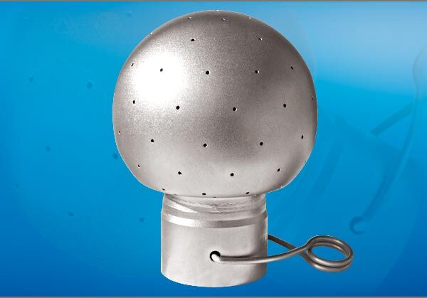
Extensive range with high quality workmanship
- 0.8 to 8.0 meter cleaning diameter
- 7 different spray pattern types available
- suitable for use in FDA & EX environment
- acid, alkali & temperature resistant
- 3 different ball sizes available
- inexpensive to purchase, reliable operation
- reasonable selection of high quality materials
| Technical Data | Value |
|---|---|
| Max. Cleaning Diameter: | 8 meters |
| Spraypattern: | 360°, 188°, 192°, 194°, 206°, 232°, 246° |
| Pressure-range: | 1,0 – 2,5 bar |
| Flowrate: | 7 – 1112 LPM (2,8 – 66,7 m³/h) |
| Insertion Opening: | 30 mm up to 95mm |
| Mounting position: | arbitrary |
| Materials: | Stainless Steel 316L (1.4404) |
| Standard connection: | 1/2″, 1″, 2″ Inch clamp connection |
| Surface: | polished, external Ra<=0.8 μm for inch, matt for DIN 11850 |
| Nozzle characteristic: | static ball with holes |
| Certificates: | 3.1 DIN EN 10204, 2.2 |
| max. Operating temperature: | 120°C (248°F) |
| max. ambient temperature: | 140°C (284°F) 30 Min. |
| Operating recommendation: | It is recommended to install a filter/strainer (500 μm) in the CIP supply line to the tank cleaner to protect it from particle clogging or damage. |
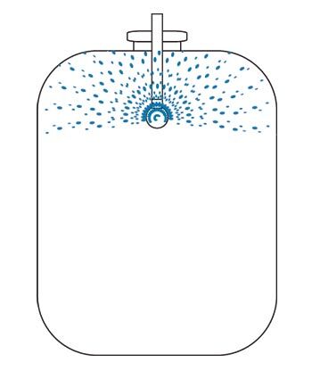
Due to high liquid volumes, fixed spray balls enable thorough cleaning even at low pressure. The cleaning effect is achieved by bombarding and rinsing the inner walls of the container. By adding suitable cleaning agents, an improvement of the cleaning effect can be achieved, thus shortening the cleaning time.
Two modes of operation are possible
– permanent flushing
– impulse-pause operation
Compared to the permanent blasting, the impulse-pause operation causes a reduction of the cleaning liquid quantity with the same cleaning time. This allows the cleaning medium used to develop its effect.
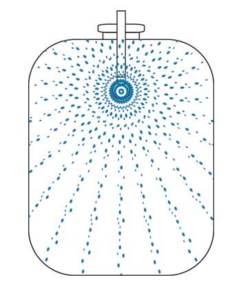
Type A/LA 360°,
vertical and
horizontal tanks
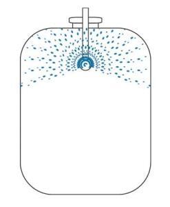
Typ B 192°-194°,
facing downwards
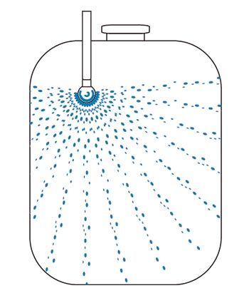
Typ G 206°-246°,
facing upwards
Typ L 188°,
facing upwards,
lying (horizontal) tanks
Pipe Types
| (DIN 11866 A-Series for Pipe outward dimensions) | DIN 11866 Reihe B DIN EN ISO 1127 | DIN 11866 Reihe C ASME-BPE 2005 | ||||||
|---|---|---|---|---|---|---|---|---|
| DR: Outer pipe dimensions s: Sprayball Wall thickness | ||||||||
| DN | DR (mm) | s (mm) | DN/OD | DR (mm) | s (mm) | DN | DR | s (mm) |
| 10 | 13 | 1,5 | 13,5 | 13,5 | 1,6 | 1/2″ | 12,7 | 1,65 |
| 15 | 19 | 1,5 | 17,2 | 17,2 | 1,6 | 3/4″ | 19,05 | 1,65 |
| 20 | 23 | 1,5 | 21,3 | 21,3 | 1,6 | |||
| 26,9 | 26,9 | 1,6 | ||||||
| 25 | 29 | 1,5 | 33,7 | 33,7 | 2,0 | 1″ | 25,4 | 1,65 |
| 40 | 41 | 1,5 | 42,4 | 42,4 | 2,0 | 1 1/2″ | 38,1 | 1,65 |
| 50 | 53 | 1,5 | 48,3 | 48,3 | 2,0 | 2″ | 50,8 | 1,65 |
 |
|---|
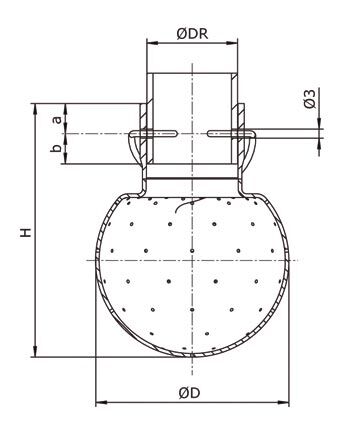
Drilling dimensions
| Typ 05 | Typ 1 | Typ 2 | ||||||||||
|---|---|---|---|---|---|---|---|---|---|---|---|---|
| 316L (1.4404) | 316L (1.4435) | Alloy 59 (2.4605) | 316L (1.4404) | 316L (1.4435) | Alloy 59 (2.4605) | 316L (1.4404) | ||||||
| Ø DR | 12 mm | 13 mm | 1/2″ OD mm | 13,5 mm | 1/2″ OD mm | 29 mm | 1″ OD mm | 29 mm | 33,7 mm | 33,7 mm | 53 mm | 2″ OD mm |
| Ø D | 28 | 28 | 28 | 28 | 28 | 64 | 64 | 64 | 64 | 64 | 93 | 93 |
| H | 46,6 | 46,6 | 46,6 | 46,6 | 46,6 | 84 | 84 | 84 | 84 | 84 | 113,5 | 113,5 |
| b+a | 18 | 18 | 16 | 18 | 18 | 20 | 20 | 20 | 16,5 | 16,5 | 30 | 30 |
| a | 10 | 10 | 8 | 10 | 10 | 10 | 10 | 10 | 6 | 6 | 10 | 10 |
| b | 8 | 8 | 8 | 8 | 8 | 10 | 10 | 10 | 10,5 | 10,5 | 20 | 20 |
| Drilling from Underside Pipe | ||||||||||||
| b-0,2 | 7,8 | 7,8 | 7,8 | 7,8 | 7,8 | 9,8 | 9,8 | 9,8 | 10,3 | 10,3 | 19,8 | 19,8 |
DIN 11850 Clamp Connection
| Type | Spray angle | Cleaning Range Ø m | 1,0 bar m³/h | 1,5 bar m³/h | 1,8 bar m³/h | 2,0 bar m³/h | 2,2 bar m³/h | 2,5 bar m³/h | D mm | H mm | Pipe DIN 11850 | Order code |
|---|---|---|---|---|---|---|---|---|---|---|---|---|
| Flow rate with electropolished spray balls approx. 15 – 20% higher than indicated in the table. Recommended operating pressure 1.0 to 2.5 bar at the inlet of the spray ball. The guideline value for cleaning fluid per metre of tank circumference is 30 to 50 l/min. | ||||||||||||
| A05 | 360° | 1,0-2,0 | 5,1 | 6,2 | 6,8 | 7,2 | 7,6 | 8,1 | 28 | 46,6 | 12 | 11850-253-109.63 |
| A05-1,0 | 360° | 0,8-1,5 | 2,8 | 3,4 | 3,8 | 4,0 | 4,2 | 4,4 | 28 | 46,6 | 12 | 11850-253-109.73 |
| A05 | 360° | 1,0-2,0 | 5,1 | 6,2 | 6,8 | 7,2 | 7,6 | 8,1 | 28 | 46,6 | 13 | 11850-253-111.40 |
| A05-1,0 | 360° | 0,8-1,5 | 2,8 | 3,4 | 3,8 | 4,0 | 4,2 | 4,4 | 28 | 46,6 | 13 | 11850-253-111.41 |
| A1-1,0 | 360° | 1,5-2,5 | 3,0 | 3,7 | 4,0 | 4,2 | 4,4 | 4,7 | 64 | 84 | 29 | 11850-254-000044 |
| A1-1,5 | 360° | 1,8-3,0 | 7,0 | 8,6 | 9,4 | 9,9 | 10,4 | 11,1 | 64 | 84 | 29 | 11850-254-000046 |
| A1 | 360° | 2,0-3,0 | 9,8 | 12,0 | 13,1 | 13,9 | 14,5 | 15,5 | 64 | 84 | 29 | 11850-254-000030 |
| A1-1 | 360° | 2,5-3,5 | 12,8 | 15,7 | 17,2 | 18,1 | 19,0 | 20,2 | 64 | 84 | 29 | 11850-254-000031 |
| A1-2 | 360° | 3,0-4,0 | 15,3 | 18,7 | 20,5 | 21,6 | 22,6 | 24,1 | 64 | 84 | 29 | 11850-254-000032 |
| A2 | 360° | 3,5-5,0 | 21,9 | 26,8 | 29,4 | 31,0 | 32,5 | 34,6 | 93 | 113,5 | 53 | 11850-254-000042 |
| A2-1 | 360° | 4,0-6,0 | 28,4 | 34,8 | 38,2 | 40,2 | 42,2 | 45,0 | 93 | 113,5 | 53 | 11850-254-000040 |
| A2-2 | 360° | 5,0-7,0 | 35,6 | 43,6 | 47,8 | 50,3 | 52,8 | 56,3 | 93 | 113,5 | 53 | 11850-254-000041 |
| A2-3 | 360° | 6,0-8,0 | 40,9 | 50,1 | 54,99 | 57,8 | 60,7 | 64,7 | 93 | 113,5 | 53 | 11850-254-000049 |
| B05 | 192° | 1,0-2,0 | 3,0 | 3,7 | 4,0 | 4,2 | 4,4 | 4,7 | 28 | 46,6 | 12 | 11850-253-109.74 |
| B1 | 192° | 2,0-3,0 | 9,5 | 11,6 | 12,7 | 13,4 | 14,1 | 15,0 | 64 | 84 | 29 | 11850-254-000033 |
| B2 | 194° | 3,5-5,0 | 22,4 | 27,4 | 30,1 | 31,7 | 33,2 | 35,4 | 93 | 113,5 | 53 | 11850-254-000050 |
| B2-3 | 194° | 6,0-8,0 | 42,2 | 51,7 | 56,6 | 59,7 | 62,6 | 66,7 | 93 | 113,5 | 53 | 11850-254-000053 |
| G05 | 232° | 1,0-2,0 | 4,7 | 5,8 | 6,3 | 6,6 | 7,0 | 7,4 | 28 | 46,6 | 12 | 11850-253-109.78 |
| G05 | 232° | 1,0-2,0 | 4,7 | 5,8 | 6,3 | 6,6 | 7,0 | 7,4 | 28 | 46,6 | 13 | 11850-253-111.46 |
| G1 | 206° | 2,0-3,0 | 9,2 | 11,3 | 12,3 | 13,0 | 13,6 | 14,5 | 64 | 84 | 29 | 11850-254-000036 |
| G1-1 | 206° | 2,5-3,5 | 11,2 | 13,7 | 15,0 | 15,8 | 16,6 | 17,7 | 64 | 84 | 29 | 11850-254-000037 |
| G1-2 | 206° | 3,0-4,0 | 14,5 | 17,8 | 19,5 | 20,5 | 21,5 | 22,9 | 64 | 84 | 29 | 11850-254-000038 |
| G2 | 246° | 3,5-5,0 | 20,1 | 24,6 | 27,0 | 28,4 | 29,8 | 31,8 | 93 | 113,5 | 53 | 11850-254-000054 |
| G2-1 | 246° | 4,0-6,0 | 26,8 | 32,8 | 36,0 | 37,9 | 39,8 | 42,4 | 93 | 113,5 | 53 | 11850-254-000055 |
| G2-2 | 246° | 5,0-7,0 | 34,7 | 42,5 | 46,6 | 49,1 | 51,5 | 54,9 | 93 | 113,5 | 53 | 11850-254-000056 |
| G2-3 | 246° | 6,0-8,0 | 41,0 | 50,2 | 55,0 | 58,0 | 60,8 | 64,8 | 93 | 113,5 | 53 | 11850-254-000057 |
| L1 | 188° | 2,5-3,0 | 8,6 | 10,5 | 11,5 | 12,2 | 12,8 | 13,6 | 64 | 84 | 29 | 11850-254-000045 |
| LA1-1,0 | 360° | 1,5-2,5 | 5,5 | 6,7 | 7,4 | 7,8 | 8,2 | 8,7 | 64 | 84 | 29 | 11850-254-000048 |
| LA1-1,5 | 360° | 2,5-3,0 | 11,0 | 13,5 | 14,8 | 15,6 | 16,3 | 17,4 | 64 | 84 | 29 | 11850-254-000047 |
Inch Clamp connection
| Type | Spay angle | Cleaning Range Ø m | 1,0 bar m³/h | 1,5 bar m³/h | 1,8 bar m³/h | 2,0 bar m³/h | 2,2 bar m³/h | 2,5 bar m³/h | D mm | H mm | Pipe Inch OD (mm) | Oder code |
|---|---|---|---|---|---|---|---|---|---|---|---|---|
| Flow rate with electropolished spray balls approx. 15 – 20% higher than indicated in the table. Recommended operating pressure 1.0 to 2.5 bar at the inlet of the spray ball. The guideline value for cleaning fluid per metre of tank circumference is 30 to 50 l/min. | ||||||||||||
| A05 | 360° | 1,0-2,0 | 5,1 | 6,2 | 6,8 | 7,2 | 7,6 | 8,1 | 28 | 46,6 | 1/2″ (12,7) | INCH-253-109.42 |
| A05-1,0 | 360° | 0,8-1,5 | 2,8 | 3,4 | 3,8 | 4,0 | 4,2 | 4,4 | 28 | 46,6 | 1/2″ (12,7) | INCH-253-111.43 |
| A1-1,0 | 360° | 1,5-2,5 | 3,0 | 3,7 | 4,0 | 4,2 | 4,4 | 4,7 | 64 | 84 | 1″ (25,4) | INCH-253-111.48 |
| A1-1,5 | 360° | 1,8-3,0 | 7,0 | 8,6 | 9,4 | 9,9 | 10,4 | 11,1 | 64 | 84 | 1″ (25,4) | INCH-253-111.49 |
| A1 | 360° | 2,0-3,0 | 9,8 | 12,0 | 13,1 | 13,9 | 14,5 | 15,5 | 64 | 84 | 1″ (25,4) | INCH-253-109.43 |
| A1-1 | 360° | 2,5-3,5 | 12,8 | 15,7 | 17,2 | 18,1 | 19,0 | 20,2 | 64 | 84 | 1″ (25,4) | INCH-253-109.44 |
| A1-2 | 360° | 3,0-4,0 | 15,3 | 18,7 | 20,5 | 21,6 | 22,6 | 24,1 | 64 | 84 | 1″ (25,4) | INCH-253-109.47 |
| A2 | 360° | 3,5-5,0 | 21,9 | 26,8 | 29,4 | 31,0 | 32,5 | 34,6 | 93 | 113,5 | 2″ (50,8) | INCH-253-109.49 |
| A2-1 | 360° | 4,0-6,0 | 28,4 | 34,8 | 38,2 | 40,2 | 42,2 | 45,0 | 93 | 113,5 | 2″ (50,8) | INCH-253-109.52 |
| A2-2 | 360° | 5,0-7,0 | 35,6 | 43,6 | 47,8 | 50,3 | 52,8 | 56,3 | 93 | 113,5 | 2″ (50,8) | INCH-253-109.54 |
| A2-3 | 360° | 6,0-8,0 | 40,9 | 50,1 | 54,9 | 57,8 | 60,7 | 64,7 | 93 | 113,5 | 2″ (50,8) | INCH-253-109.59 |
| B05 | 192° | 1,0-2,0 | 3,0 | 3,7 | 4,0 | 4,2 | 4,4 | 4,7 | 28 | 46,6 | 1/2″ (12,7) | INCH-253-111.44 |
| B1 | 192° | 2,0-3,0 | 9,5 | 11,6 | 12,7 | 13,4 | 14,1 | 15,0 | 64 | 84 | 1″ (25,4) | INCH-253-109.50 |
| B2 | 194° | 3,5-5,0 | 22,4 | 27,4 | 30,1 | 31,7 | 33,2 | 35,4 | 93 | 113,5 | 2″ (50,8) | INCH-253-111.51 |
| B2-3 | 194° | 6,0-8,0 | 42,2 | 51,7 | 56,6 | 59,7 | 62,6 | 66,7 | 93 | 113,5 | 2″ (50,8) | INCH-253-111.54 |
| G05 | 232° | 1,0-2,0 | 4,7 | 5,8 | 6,3 | 6,6 | 7,0 | 7,4 | 28 | 46,6 | 1/2″ (12,7) | INCH-253-111.45 |
| G1 | 206° | 2,0-3,0 | 9,2 | 11,3 | 12,3 | 13,0 | 13,6 | 14,5 | 64 | 84 | 1″ (25,4) | INCH-253-109.06 |
| G1-1 | 206° | 2,5-3,5 | 11,2 | 13,7 | 15,0 | 15,8 | 16,6 | 17,7 | 64 | 84 | 1″ (25,4) | INCH-253-109.45 |
| G1-2 | 206° | 3,0-4,0 | 14,5 | 17,8 | 19,5 | 20,5 | 21,5 | 22,9 | 64 | 84 | 1″ (25,4) | INCH-253-109.48 |
| G2 | 246° | 3,5-5,0 | 20,1 | 24,6 | 27,0 | 28,4 | 29,8 | 31,8 | 93 | 113,5 | 2″ (50,8) | INCH-253-109.07 |
| G2-1 | 246° | 4,0-6,0 | 26,8 | 32,8 | 36,0 | 37,9 | 39,8 | 42,4 | 93 | 113,5 | 2″ (50,8) | INCH-253-109.53 |
| G2-2 | 246° | 5,0-7,0 | 34,7 | 42,5 | 46,6 | 49,1 | 51,5 | 54,9 | 93 | 113,5 | 2″ (50,8) | INCH-253-109.55 |
| G2-3 | 246° | 6,0-8,0 | 41,0 | 50,2 | 55,0 | 58,0 | 60,8 | 64,8 | 93 | 113,5 | 2″ (50,8) | INCH-253-111.55 |
| L1 | 188° | 2,5-3,0 | 8,6 | 10,5 | 11,5 | 12,2 | 12,8 | 13,6 | 64 | 84 | 1″ (25,4) | INCH-253-111.37 |
| LA1-1,0 | 360° | 1,5-2,5 | 5,5 | 6,7 | 7,4 | 7,8 | 8,2 | 8,7 | 64 | 84 | 1″ (25,4) | INCH-253-111.65 |
| LA1-1,5 | 360° | 2,5-3,0 | 11,0 | 13,5 | 14,8 | 15,6 | 16,3 | 17,4 | 64 | 84 | 1″ (25,4) | INCH-253-111.62 |
Installation Lance

| Materials: | Stainless Steel 1.4404 (316L), EPDM, FKM |
| Certificate: | 3.1, 2.2 |
| Device Connection: | see Table |
| Tank connection: | Flange on demand |
| Sensor: | without SMW 100 |
Die dargestellten Angaben, technischen Daten und Informationen befreien den Anwender nicht von eigener Prüfung der gelieferten Produkte auf deren Eignung für den beabsichtigten Anwendungsfall. Alle Angaben sind ohne Gewähr. (Stand: 26.07.2022-71427321893-1888948-71042)
