2E/2B Strahlreiniger
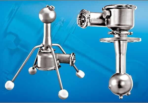
The 2E/2B jet cleaner is available as a standing or suspended rotary cleaner
- effective cleaning effect
- compact installation
- also with rotation control
- hygienic design FDA compliant
- validatable cleaning process
- energy-saving drive technology
- different connection possibilities
| Technical Data | Value |
|---|---|
| Max. Cleaning Diameter: | 2E 10meters / 2B 6 meters |
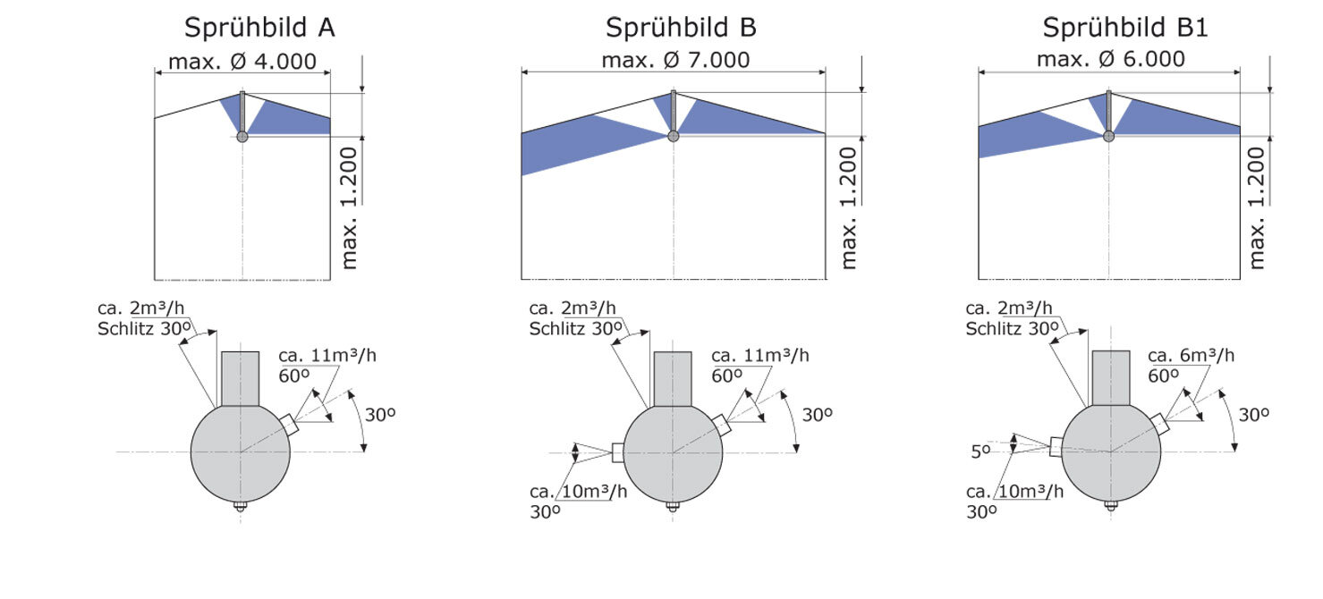
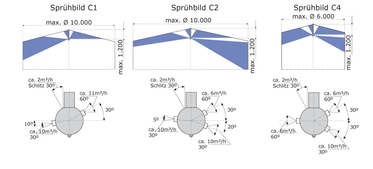
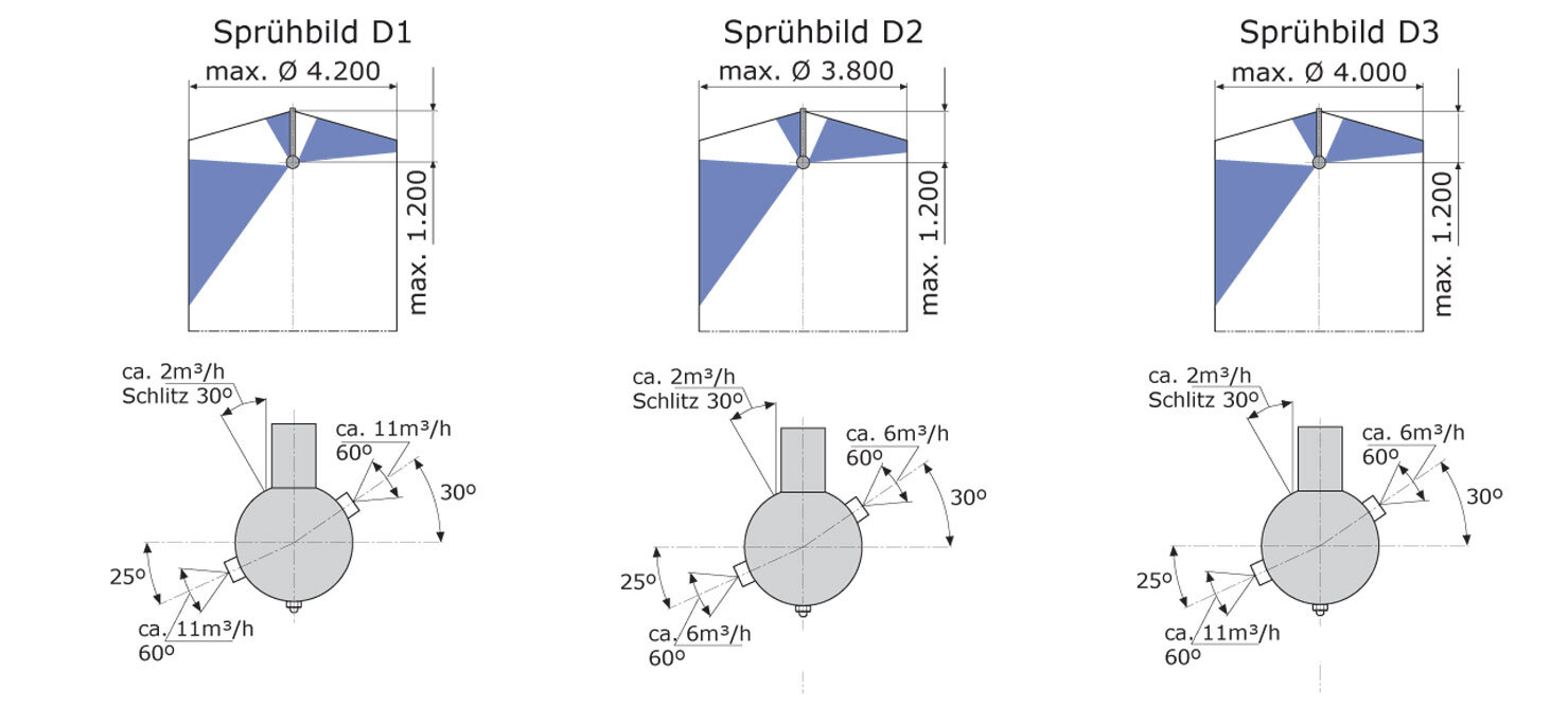
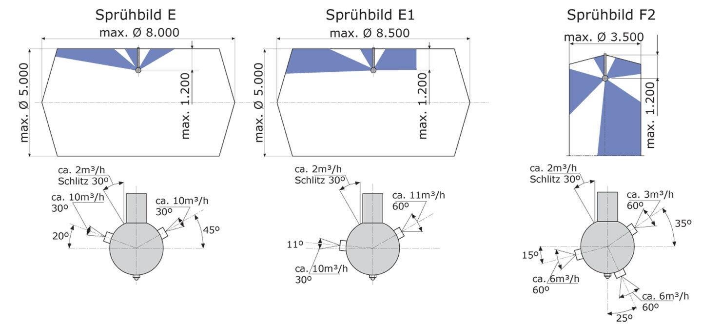
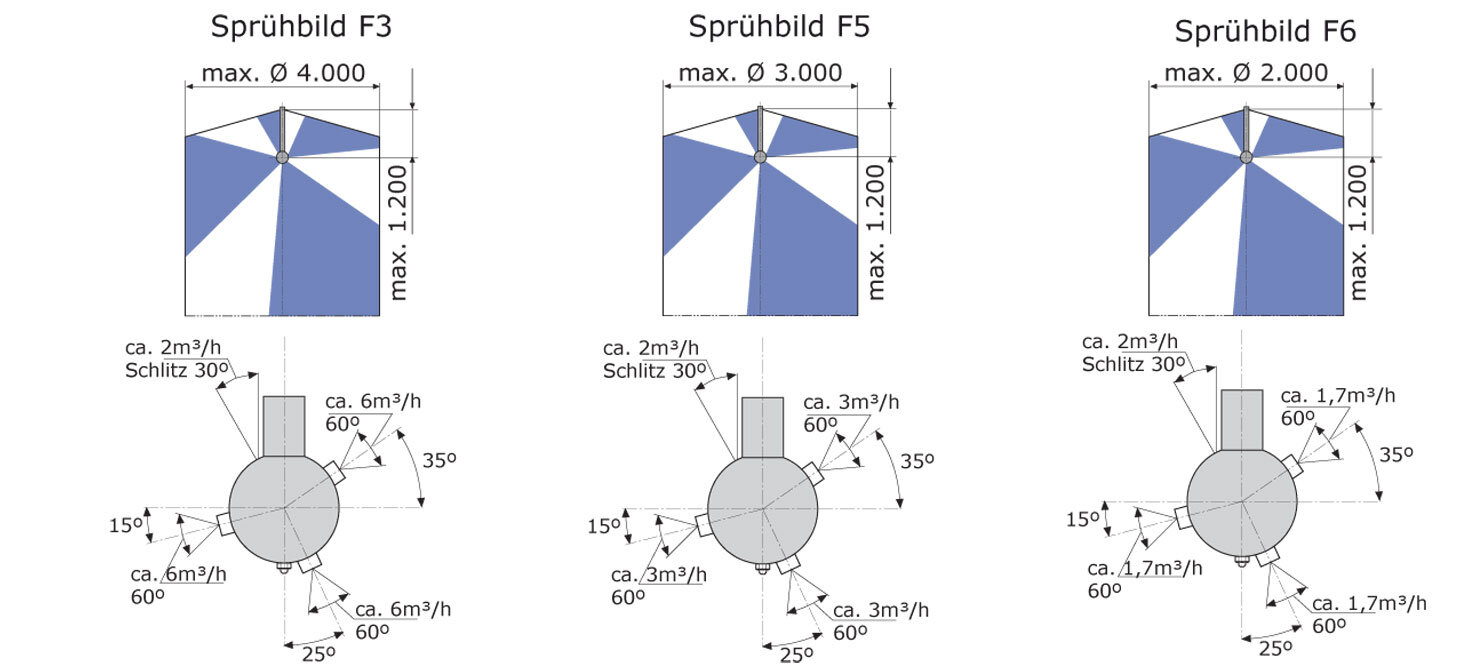
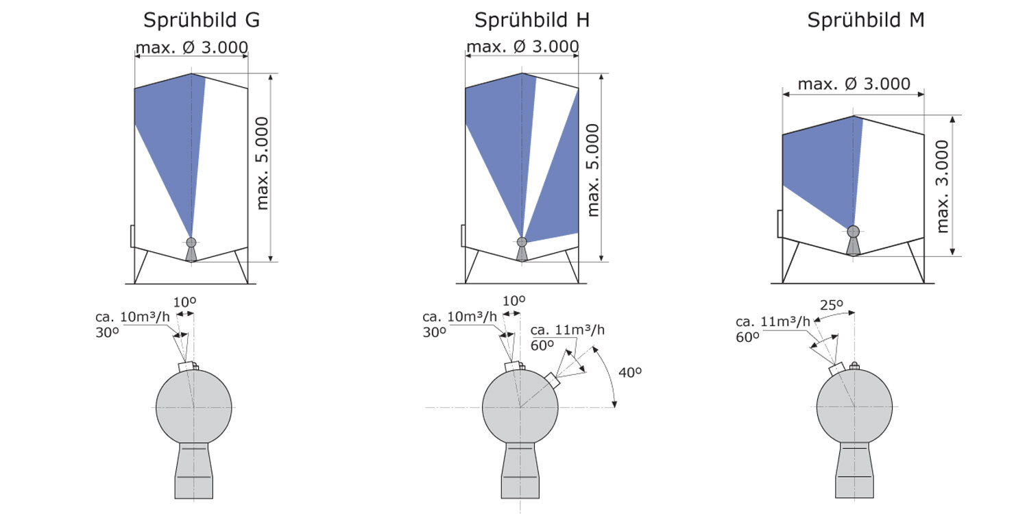
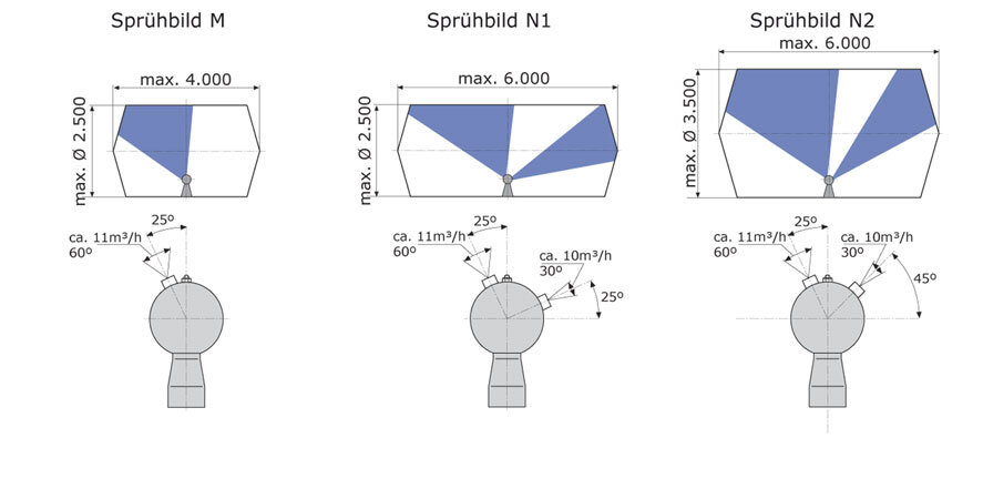
| Spraypattern: | see spray image graphics below |
| Pressure-range: | 2E 2,3 – 4,3 bar / 2B 2,3 – 3,2 bar |
| Flowrate: | 2E 117 – 483 LPM (7,0 – 29,0 m³/h) / 2B 167 – 367 LPM (10,0 – 22,0 m³/h) |
| Insertion Opening: | 2E min. Ø 100 mm / 2B min. Ø 440 mm |
| Mounting position: | vertically downwards hanging / standing |
| Weight: | 2E ca. 11 KG / 2B ca. 15 KG |
| Materials: | Stainless Steel 316Ti (1.4571), PP, PTFE, EPDM |
| Nozzle characteristic: | 15 spray types model 2E, 5 spray types model 2B |
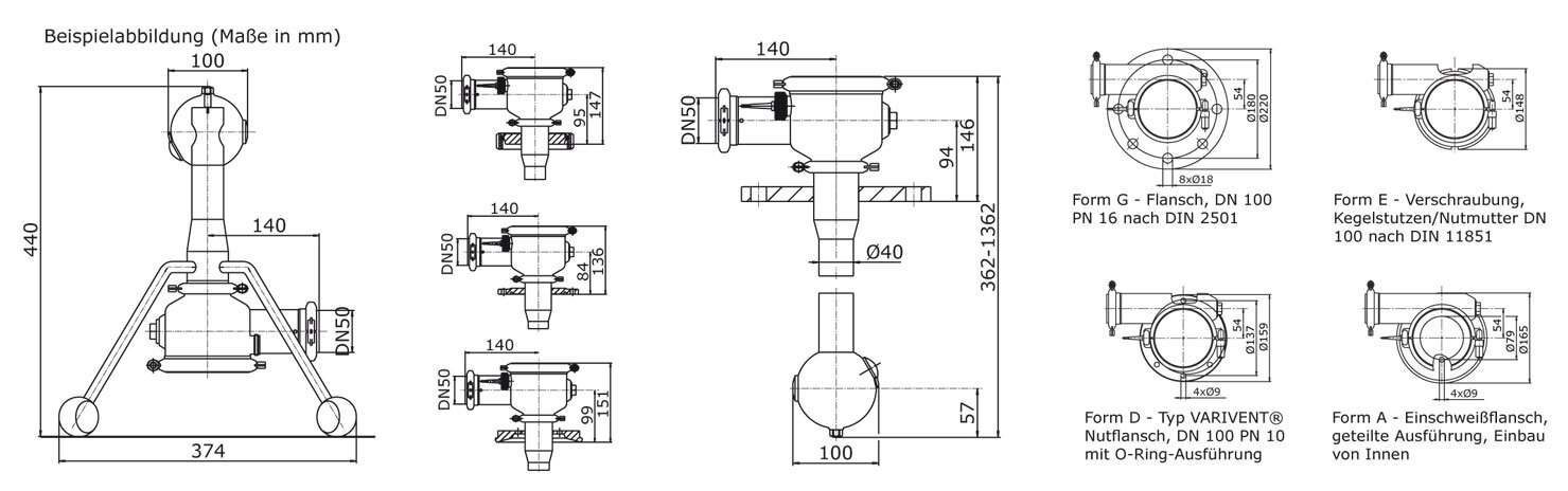
| Insertion Lenght: | 200 up to 1.200 mm |
| Certificates: | 2.2 DIN EN10204, more on demand |
| max. Operating temperature: | with PP 80°C (176°F), with PTFE 90°C (194°F) |
| max. ambient temperature: | with PP 80°C (176°F), with PTFE 130°C (266°F), 30 Min. |
| Operating recommendation: | It is recommended to install a filter/strainer (500 μm) in the CIP supply line to the tank cleaner to protect it from particle clogging or damage. |
- Interval rinsing by slowly circulating fan jets
- Multiple increased surge compared to spray balls
- Various spray patterns due to different nozzle arrangements
- Liquid drive via flow gears
- Function monitoring by proximity switch (optional)
- Various options for pressure and tank connections
2E Jet cleaner
| Typ 2E | Nozzles count | Flowrate m³/h | Pressure bar | Rotations minˉ¹ | Cleaning Ø m |
|---|---|---|---|---|---|
| Typ A | 1 | 13 – 14 | 2,7 | 8 – 12 | 4 |
| Typ B | 2 | 23 – 24 | 3,7 | 4 – 6 | 7 |
| Typ B1 | 2 | 18 – 19 | 3,0 | 3 – 4 | 6 |
| Typ C1 | 2 | 23 – 24 | 3,7 | 4 – 6 | 10 |
| Typ C2 | 3 | 28 – 29 | 4,3 | 5 – 8 | 10 |
| Typ C4 | 3 | 24 – 25 | 3,9 | 5 – 7 | 6 |
| Typ D1 | 2 | 24 – 25 | 3,8 | 4 – 6 | 4,2 |
| Typ D2 | 2 | 14 – 15 | 2,8 | 3 – 4 | 3,8 |
| Typ D3 | 2 | 19 – 20 | 3,4 | 4 – 5 | 4 |
| Typ E | 2 | 22 – 23 | 3,6 | 4 – 6 | 8 |
| Typ E1 | 2 | 23 – 24 | 3,7 | 4 – 6 | 8,5 |
| Typ F2 | 3 | 17 – 18 | 2,8 | 3 – 5 | 3,5 |
| Typ F3 | 3 | 20 – 21 | 3,2 | 3 – 5 | 4 |
| Typ F5 | 3 | 11 – 12 | 2,6 | 6 – 10 | 3 |
| Typ F6 | 3 | 7 – 8 | 2,3 | 4 – 6 | 2 |
2B Jet cleaner
| Typ 2B | Nozzles count | Flowrate m³/h | Pressure bar | Rotations minˉ¹ | Cleaning Ø m |
|---|---|---|---|---|---|
| Typ G | 1 | 10 – 11 | 2,3 | 7 – 10 | 3 |
| Typ H | 2 | 21 – 22 | 3,2 | 4 – 6 | 3 |
| Typ M | 1 | 11 – 12 | 2,4 | 7 – 10 | 3 – 4 |
| Typ N1 | 2 | 21 – 22 | 3,2 | 4 – 6 | 6 |
| Typ N2 | 2 | 21 – 22 | 3,2 | 4 – 6 | 6 |
2E/2B Jet cleaner
| Code | RTZR | 2E | 2 | 600 | 00 | 3 | 10 | C2 | 0 | M | K |
|---|---|---|---|---|---|---|---|---|---|---|---|
| Position | 1 | 2 | 3 | 4 | 5 | 6 | 7 | 8 | 9 | 10 | 11 |
| Example | Position | Designation | Code-Selction Characters | |
|---|---|---|---|---|
| RTZR | 1 | Typ | RTZR = Jet cleaner | IS25 DN25 |
| 2E | 2 | variant | 2E | hanging |
| 2B | standing | |||
| 2 | 3 | Material | 2 | 1.4571 (316Ti)/PP |
| 3 | 1.4571 (316Ti)/PTFE5 | |||
| 600 | 4 | Insertion lenght | 200 = 200 mm, 400 = 400 mm, 600 = 600 mm | |
| 800 = 800 mm, 1000 = 1000 mm, 1200 = 1200 mm | ||||
| 00 | 5 | Tank connection for ZR 2E | 00 | without Tank connection |
| 02 | Form F Flange, DN 80 PN 6 DIN 2501 | |||
| 03 | Form G Flange, DN 100 PN 16 DIN 2501 | |||
| 04 | Form E Cone Locknut, DN 100 DIN 11851 | |||
| 06 | Form H Cone Locknut, DN 80 DIN 11851 | |||
| 08 | Form A Welding Flange, seperated variant | |||
| 09 | Form D VARIVENT® NutFlange, 4″ OD PN 10 | |||
| 10 | Form D VARIVENT® NutFlange, DN 100 PN 10 | |||
| 13 | Form D VARIVENT® NutFlange, DN 125 PN 10 | |||
| 14 | Form D VARIVENT® NutFlange, DN 162 PN 10 | |||
| 5 | Positioning block for ZR 2B | 11 | Positioning block for Manhole | |
| 3 | 6 | Pressure connection | 1 | Clamping ring connection DN 50 |
| 2 | Threaded connection DN 50 DIN 11851 | |||
| 3 | VARIVENT® NutFlange, DN 50 PN 16 | |||
| 4 | Pipe fitting DN 50 DIN 11851 | |||
| 5 | VARIVENT® Flange connection DN 50 PN 16 kpl. | |||
| 10 | 7 | Feedback | 1 | Connection for Initiator, blind set |
| 10 | Initiator 8,2 V DC (Namur) | |||
| 11 | Initiator 10-30 V DC (3-wire) | |||
| 21 | Initiator 20-250 V AC (2-wire) | |||
| 33 | Only Initiator sleeve made of PTFE | |||
| C2 | 8 | Nozzle arrangement 2E | A, B, B1, C1, D1, D2, D3, E, E1, | |
| C2, C4, F2, F3, F5, F6 | ||||
| 8 | Nozzle arrangement 2B | G, M, | ||
| H, N1, N2 | ||||
| 0 | 9 | Counter Flange Tank connection | 0 | Without Counter Flange |
| 1 | Flange seal Form F | |||
| 3 | Counter Flange Form F kpl. | |||
| 4 | VARIVENT® smooth flange DN 100 / 4″ OD | |||
| 4 | VARIVENT® smooth flange DN 125 | |||
| 4 | VARIVENT® smooth flange DN 162 | |||
| 5 | Manhole apron | |||
| M | 10 | Surface | M | matte |
| E | electro polished | |||
| K | 11 | Certificates | K | without Certificates |
| W | (41) mit Work certificate 2.2 DIN EN10204 | |||
The data, technical data and information presented do not release the user from the obligation to check the suitability of the products supplied for the intended application. All data are without guarantee. (Stand: 29.10.2023-71427321893-1888948-71042)